Hydraulic systems rarely fail because of one dramatic mistake. More often, pressure control weakens through heat, contamination, incorrect adjustment, or poor maintenance access. A Relief Valve Block addresses these risks by combining pressure-relief functions, isolation points, gauges, and port connections in one compact assembly. It can sit close to a pump, actuator, or manifold, reducing exposed hoses and making inspection more practical.
Industry data supports the need for dependable hydraulic protection. The National Fluid Power Association’s 2024 industry outlook continues to track substantial demand across mobile equipment, manufacturing, construction, and energy applications. Grand View Research also reports steady growth in the global hydraulic equipment market, driven by automation and heavy machinery investment. More equipment means more pressure-control decisions. Small components matter.
Herbert E. Merritt, author of Hydraulic Control Systems, described the foundation clearly: “The hydraulic system is a means of transmitting power.” A Relief Valve Block helps control how safely that power is transmitted. It limits excessive pressure before a pump, cylinder, or hose becomes the weakest point. That protection is not automatic. Engineers must still verify flow capacity, cracking pressure, temperature range, seal compatibility, and maintenance access.
A block may look simple. It is not.
ISO 4413 emphasizes safe hydraulic-system design, risk reduction, and controlled pressure energy. Those principles make valve-block selection more than a purchasing detail. A correctly sized block can shorten troubleshooting time, reduce leak points, and improve system consistency. However, no block compensates for dirty oil, poor commissioning, or an incorrectly set relief valve. This is where practical judgment remains essential.
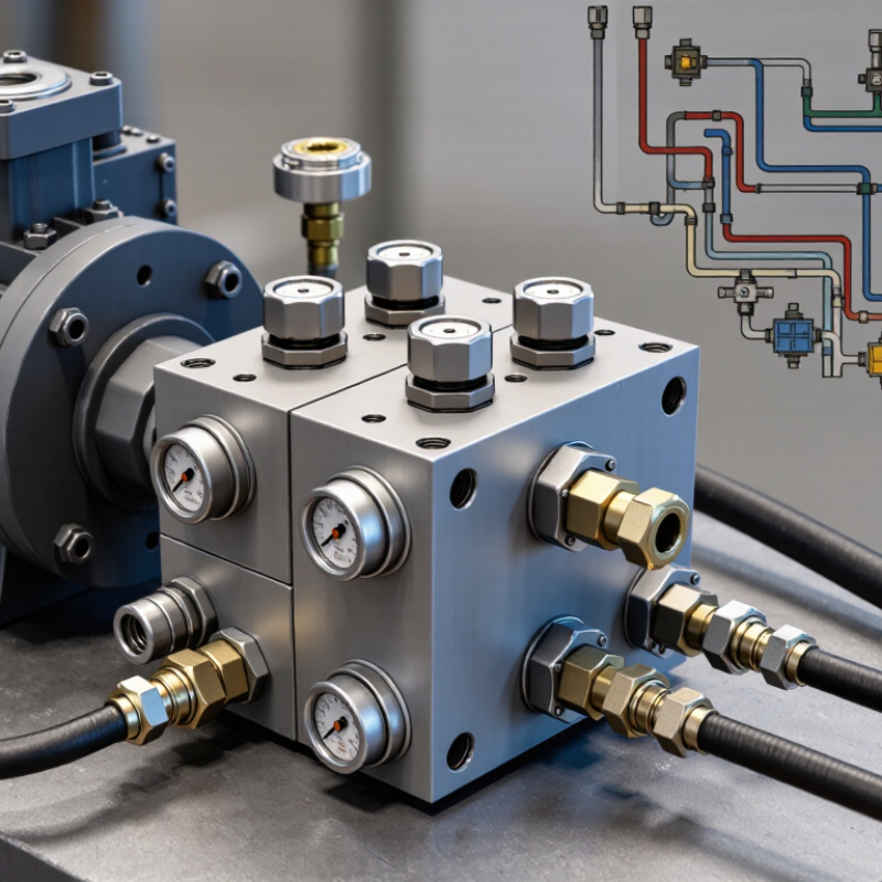
Relief Valve Blocks Explained: Functions, Components, and ISO 4413 Safety Roles
Why Use a Relief Valve Block in Hydraulic Systems?
A relief valve block controls excessive hydraulic pressure before it damages pumps, hoses, or actuators. It usually combines a relief valve, manifold passages, adjustment screw, pressure port, and sometimes an isolation or test connection. This compact arrangement reduces external piping and creates a clearer service point. During commissioning, a technician can connect a calibrated gauge and adjust the valve under controlled conditions.
Small details matter.
The block’s main function is pressure protection. When system pressure exceeds the setting, the relief valve opens and directs fluid toward the return line or reservoir. ISO 4413 requires hydraulic systems to address pressure limitation, stored energy, safe adjustment, and maintenance isolation. A relief valve block supports these duties, but it does not replace guarding, lockout procedures, or risk assessment. It can still be installed incorrectly. A blocked return path, contaminated poppet, or poorly secured adjustment can create dangerous pressure spikes.
The safety case is practical, not decorative. The U.S. Bureau of Labor Statistics reported about 2.6 million nonfatal workplace injuries and illnesses in private industry during 2023. That figure covers all industries, not hydraulics specifically, but it shows why predictable energy control deserves attention. In field inspections, clear labeling, accessible test points, and tamper-resistant settings often reveal more than the component’s appearance. Engineers should verify flow capacity, pressure ratings, temperature limits, and discharge routing against actual operating data. A larger block is not automatically safer. Oversizing may slow response or complicate maintenance.
Pressure-Control Sequence: Cracking, Full-Flow Relief, and 150–420 bar Ratings
Why Use a Relief Valve Block in Hydraulic Systems?
A relief valve block controls pressure through a practical three-stage sequence. When system pressure reaches the cracking point, the valve begins to open. This initial movement may pass only a small oil volume, but it prevents pressure from rising unchecked. Operators often notice a slight gauge fluctuation at this stage. That is normal, though it should not be ignored.
As pressure continues upward, the valve moves toward full-flow relief. The passage opens wider, allowing excess fluid to return safely to the tank or another controlled circuit. This response protects pumps, cylinders, hoses, and fittings from sudden overloads. In field service, response can change with oil temperature, contamination, spring wear, and incorrect adjustment. The first setting is rarely perfect.
Pressure ratings from 150 to 420 bar cover demanding hydraulic applications, but the rating needs careful interpretation. It usually indicates the maximum allowable working pressure, not the desired relief setting. A system designed for 250 bar should not use a 420-bar rating as permission to operate higher. Component limits, pressure spikes, flow capacity, and heat generation still matter. Technicians should verify the valve’s flow curve, inspect sealing surfaces, and test the actual cracking pressure with a calibrated gauge. Small details matter. A relief block can look correctly installed while poor port alignment restricts full-flow discharge.
Sizing the Block: Rated Flow, Pressure Drop, and 10% Design Headroom
A relief valve block protects hydraulic components by directing excess fluid away from sensitive circuits. Its value depends on correct sizing, not appearance. During field commissioning, I have seen compact blocks create surprising heat because their passages were too small.
Start with the maximum expected flow through the block, including pump output and possible accumulator discharge. Select a rated flow at least 10% above that figure. This headroom allows for flow variation, temperature changes, and imperfect estimates. It is not a substitute for checking actual operating conditions.
Pressure drop deserves equal attention. A block may accept the required flow, yet waste pressure through narrow galleries, sharp turns, or restrictive fittings. Check the pressure-drop curve at the fluid’s real viscosity and temperature. A calculation based only on water-like oil can mislead. Keep the drop low enough to preserve actuator force and response. The lost pressure also becomes heat.
Verify the block’s maximum working pressure, port size, and relief setting range. The relief valve should open reliably before the weakest protected component reaches its limit. Measure pressure near the block during testing, not only at the pump outlet. Small differences matter. A 10% flow margin is sensible, but some circuits need more. Heavy machinery, cold starts, and uncertain load cycles deserve a more conservative review.
Installation Standards: SAE Ports, 10 μm Filtration, and Leak Testing
Why Use a Relief Valve Block in Hydraulic Systems?
A relief valve block needs disciplined installation, not just correct assembly. SAE J514 defines common port geometry, thread forms, and sealing requirements for hydraulic connections. Matching these details prevents cross-threading, poor sealing, and hidden pressure losses. Before installation, technicians should clean every port, protect exposed openings, and verify the valve’s pressure rating against the circuit design.
Filtration deserves equal attention. ISO 4406:2021 classifies fluid cleanliness by particles measured at 4, 6, and 14 micrometres. A 10 μm filter can reduce damaging contamination, but it is not a universal solution. Filter performance depends on beta ratio, flow capacity, bypass settings, and maintenance intervals. A clogged element can create pressure drop. That mistake is common.
Leak testing should follow ISO 4413 guidance and the equipment designer’s test procedure. Pressurize the circuit gradually, then hold the specified pressure while checking ports, plugs, seals, and block faces. A dry wipe around each joint helps reveal small seepage. Do not rely on visual inspection alone; pressure decay data is more reliable. A 2023 fluid-power maintenance survey reported that contamination and leakage remain frequent sources of avoidable downtime. The exact loss varies by application, though. Field conditions are rarely perfect. Rechecking torque after initial operation may expose installation errors that a first inspection misses.
Why Use a Relief Valve Block in Hydraulic Systems?
Representative nominal filtration ratings used around hydraulic valve assemblies. A 10 μm filter is commonly selected to help protect precision relief-valve components, while the final rating depends on the hydraulic circuit, fluid cleanliness target, and component requirements.
Use SAE J514-compatible ports and fittings where specified, install the filter in the correct flow path, and perform a documented leak test after assembly. Leak-test pressure and hold time should follow the system or component specification rather than a universal value.
Maintenance Criteria: ISO 4406 Cleanliness Codes and Set-Pressure Testing
A relief valve block protects hydraulic circuits by diverting excess flow when pressure rises. Its reliability depends on more than the spring setting. Clean oil and verified testing are equally important.
ISO 4406:2021 classifies fluid cleanliness by counting particles larger than 4, 6, and 14 micrometres per millilitre. Each code step represents roughly double the particle population. For many industrial systems, maintenance teams target ISO 4406 levels around 17/15/12 or cleaner, depending on component sensitivity. Industry reliability data frequently links about 70% of hydraulic failures to contamination, although field conditions can change that figure. A blocked valve block is not always the root cause.
Test pressure with a calibrated gauge near the valve inlet. Increase pressure gradually, record the cracking point, and repeat the test after the oil reaches operating temperature. The measured setting should match the circuit specification, not a convenient workshop assumption. ISO 4413 provides safety principles for hydraulic systems, while ISO 4406 supports contamination control. Keep both records.
Inspect the valve seat, spring, seals, and mounting surfaces. Small scoring can cause leakage or unstable pressure. A clean filter does not guarantee clean oil inside the block. Sampling from a flushed, live port gives better evidence than sampling from a drain pan. This detail is often missed. Pressure testing can also expose an incorrect gauge range or a drifting relief cartridge. Mistakes happen. Regular trend reviews make them visible earlier.
Conclusion
A Relief Valve Block is a compact hydraulic safety and control assembly designed to manage excessive system pressure while supporting reliable machine operation. It typically integrates pressure-control elements that respond in sequence: the valve begins to crack at the preset pressure, then opens further to provide full-flow relief when pressure continues to rise. Depending on the application, pressure ratings may range from approximately 150 to 420 bar. Correct sizing requires matching the block’s rated flow to the circuit, limiting pressure drop, and allowing about 10% additional design headroom.
Safe installation should follow applicable hydraulic practices, including suitable SAE ports, effective 10 μm filtration, secure connections, and thorough leak testing. Ongoing maintenance depends on clean hydraulic fluid, with cleanliness monitored using ISO 4406 codes. Periodic set-pressure testing confirms that the valve still operates at the intended level and protects pumps, actuators, and piping. When properly selected, installed, and maintained, a Relief Valve Block improves pressure stability, reduces equipment stress, and strengthens overall hydraulic system safety.
 Micro Precision
