
Micro Precision Micro Precision

How to Choose the Right Cylinder Mounting Base?

Time:2026-11-06 Author:Oliver
0%

A Cylinder Mounting Base may look like a small part, but it transfers force, limits movement, and helps keep a cylinder aligned. A poor match can cause vibration, uneven wear, or extra stress around the mounting points. The choice depends on more than bore size. Consider the cylinder’s stroke, load direction, operating speed, available space, and how the assembly will be serviced. Small details matter. A side load from a bracket, for example, can change how the cylinder behaves over time.

Automation makes dependable mounting decisions increasingly important. The International Federation of Robotics’ World Robotics 2024 report states that 4,281,585 industrial robots were operating in factories worldwide in 2023, a 10% increase from 2022. That figure describes robot installations, not cylinder bases, but it reflects the wider demand for reliable industrial equipment. ISO 15552 also specifies dimensions and interchangeable mounting interfaces for certain pneumatic cylinders; it does not select the right base for every application. That part still requires engineering judgment. And judgment can be imperfect. A base that fits neatly on a drawing may be difficult to reach with a wrench, or may flex under a real operating load. This guide explains how to compare mounting styles, materials, alignment needs, and installation constraints, so the final choice works on the machine—not just on paper.
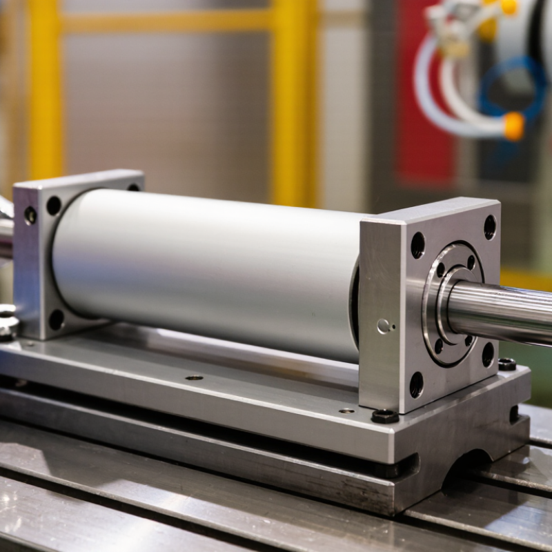
How to Choose the Right Cylinder Mounting Base?

Cylinder Mounting Bases: Types and Key Functions

Cylinder mounting bases secure a cylinder to a machine frame and help transfer operating forces into the structure. Common types include foot, flange, trunnion, and clevis mounts. Foot bases support the cylinder body along its length, making them useful where side access is available. Flange mounts attach at an end face and suit compact layouts. Trunnion and clevis mounts allow pivoting, which can accommodate a moving linkage.

Each type handles alignment and motion differently. A rigid foot or flange base can keep a cylinder steady, but it may bind if the rod and load are not aligned. Pivoting mounts tolerate angular movement, though their pins and supports still need to handle the expected force. Fit matters. Check bolt spacing, base thickness, available clearance, and the frame material. A thin plate may flex under repeated cycles, even when the mount itself looks substantial.

Choose the base around the load direction, stroke, speed, and installation space. For example, a cylinder pushing a sliding fixture may need firm support against sideways force; a hinged mechanism may need a pivoting mount. Not always. More metal does not automatically mean better support, because added bulk can restrict movement or complicate installation. Compare the mounting drawing with the actual machine, and inspect for contact points that could shift as the cylinder extends.

Assessing Cylinder Load, Stroke, and Operating Requirements

A cylinder mounting base must carry more than the cylinder’s own weight. Estimate the moving load, friction, acceleration, and any side force, then compare them with the base’s rated capacity. Small loads still matter. An offset load can create a bending moment, especially when a long-stroke cylinder extends and its rod is poorly aligned. Check the whole setup. Include the workpiece, tooling, and the direction of travel, not just the actuator’s catalog force. ISO 15552 standardizes key dimensions for certain pneumatic cylinders, but dimensional compatibility does not confirm that a base can withstand your application’s loads.

Stroke and operating conditions change the selection. A longer stroke can increase deflection and make alignment more sensitive; frequent starts or high speeds add dynamic loads. Check the manufacturer’s allowable moments and support conditions, and leave room for the rod to move without binding. The U.S. Department of Energy’s 2016 Improving Compressed Air System Performance sourcebook estimates compressed air uses about 10% of industrial electricity, though actual facility use varies. That figure makes leakage and unnecessary cycling worth checking when setting operating requirements. I would still recheck the load estimate after installation: real friction, vibration, and mounting surfaces rarely match a neat calculation. ISO 4414 provides relevant safety guidance for pneumatic systems, but application-specific engineering checks remain essential.

Matching the Mounting Base to the Cylinder Configuration

A mounting base should match both the cylinder’s end configuration and the way it will move under load. Start by checking the cylinder drawing for mounting style, bore size, end-cap dimensions, and fastener pattern. A base that looks close may still shift the rod centerline.

Foot mounts suit cylinders that need firm support along a fixed path. They work best when the load stays aligned with the rod. Keep it straight. If the cylinder must pivot, a clevis or trunnion mount can allow movement without forcing the barrel to twist. Check the pivot pin diameter and available swing angle, especially where nearby guards or frames limit clearance.

For tie-rod cylinders, confirm whether the base attaches to the tie rods or the end cap, and verify the specified hardware and tightening method. Longer strokes may need extra support to reduce vibration or sag. Small details matter. One easy-to-miss issue is that a base can fit the cylinder yet place the rod slightly off-axis. Check alignment with the cylinder fully installed, not only on a drawing. Measuring twice feels cautious, but side loading can shorten seal life and make motion uneven.

How to Choose the Right Cylinder Mounting Base? - Matching the Mounting Base to the Cylinder Configuration

Cylinder Configuration or Motion Mounting Base / Style to Consider Why It Fits Selection Checks Typical Applications
Linear motion with a rigidly supported cylinder Foot-mounted base Provides a simple fixed attachment when the cylinder body does not need to pivot. Support the full mounting surface; check bolt size, spacing, base stiffness, and the moment created by the force line. Avoid using the rod to carry side load. Machine frames, conveyors, and general-purpose linear actuators.
Axial push or pull with a fixed cylinder body Head or cap-end flange mount A flange attaches the cylinder end directly to a rigid support and can provide a compact, fixed mounting arrangement. Match the flange pattern and mounting face to the cylinder. Confirm which end is loaded and follow the cylinder maker’s allowable load and mounting guidance. Presses, fixtures, and equipment with a rigid bulkhead or machine plate.
Axial force with the rod-end area used as the attachment point Rod-end flange mount, where available for the cylinder configuration Places the cylinder support near the rod end while keeping the barrel fixed relative to the structure. Check the specific cylinder’s approved mounting arrangement, fastener access, force direction, and clearance throughout the stroke. Installations requiring a rod-end-side support face or a particular equipment layout.
Linear stroke with angular movement at the rod connection Clevis mount with a compatible pin connection Allows the cylinder to pivot in one plane as the connected mechanism changes angle. Align the clevis pin with the intended pivot axis. Check pin fit, retention, articulation range, and that the linkage does not impose unintended side load. Hinged guards, linkages, gates, and reciprocating mechanisms.
Cylinder body must pivot around a fixed axis Trunnion mount Trunnions support the cylinder on a pivot axis, allowing the body to swing as the mechanism moves. Position supports to match the trunnion locations. Keep the pivot axis aligned and check support stiffness, bearing or bushing arrangement, and full movement clearance. Mobile equipment, tilting mechanisms, and machinery with a moving cylinder body.
Tie-rod cylinder with an approved end-mount pattern Tie-rod extension mount or compatible flange / clevis accessory Uses a mounting arrangement designed for the cylinder’s tie rods and end-cap configuration. Verify tie-rod size, extension pattern, accessory compatibility, and permitted pressure and load conditions. Do not assume mounting accessories are interchangeable between cylinder series. Industrial pneumatic or hydraulic systems using tie-rod cylinders.
Any configuration with a long stroke or compressive loading Mount selected with stroke, alignment, and rod support in mind Longer extensions can increase the risk of rod deflection or buckling under compression; the mounting style alone does not remove that risk. Check stroke, rod diameter, unsupported length, force direction, alignment, and the cylinder manufacturer’s buckling and side-load limits. Consider external guidance if the application requires it. Long-stroke presses, lift mechanisms, and applications with extended rod travel.

Selection note: Confirm mounting dimensions, allowable loads, operating pressure, stroke, and accessories against the documentation for the exact cylinder. A mounting base should support the intended force path while keeping the cylinder and connected mechanism properly aligned.

Checking Space, Alignment, and Environmental Conditions

Choosing a cylinder mounting base starts with the space around the machine, not just the cylinder dimensions. Measure the available footprint, mounting-hole spacing, and clearance at both ends of the stroke. Include room for fittings, hoses, and tools used during maintenance. A base that fits on paper may block a wrench in practice. Small gaps matter.

Check alignment with the cylinder’s travel path and the connected load. Even slight angular mismatch can add side force, wear seals, or cause uneven movement. Use a straightedge or alignment tool across the mounting faces, and confirm that the base sits flat before tightening fasteners. If shims seem necessary, investigate why; they can help, but they may also hide a poor fit. Verify the setup through the full stroke, not only at rest.

The surrounding environment can change the choice. Dust, moisture, washdown, heat, and vibration may affect materials, coatings, and fastener security. Look for signs of corrosion or loose hardware during routine inspections. Dust changes the picture. I have seen a clean indoor layout become less predictable after nearby processes began producing fine debris. Allow for those real conditions, and check the cylinder and base specifications before installation.

Verifying Compatibility and Installation Requirements

How to Choose the Right Cylinder Mounting Base?
Verifying Compatibility and Installation Requirements

A mounting base must match the cylinder’s interface, bore, stroke, and direction of movement. Check the hole pattern and fastener size against the cylinder drawing, not just the product description. Then assess the load path: a base that fits can still flex under repeated acceleration. For pivoting applications, confirm the mount allows the intended movement without forcing the rod sideways. Small gaps matter.

Before installation, compare the assembly’s pressure and operating conditions with the cylinder and mount specifications. Keep the cylinder centerline aligned with the driven mechanism, and use a flat, clean mounting surface. Tighten fasteners to the equipment maker’s stated torque; bolts should not pull a misaligned base into place. The U.S. Department of Energy’s Improving Compressed Air System Performance sourcebook reports that compressed air systems use about 10% of industrial electricity, while leaks can waste 20–30% of compressor output. That figure concerns whole systems, not mounting bases, but it underlines why checking connections and alignment is worthwhile. I still recheck clearance through the full stroke; drawings can miss a nearby guard or cable. Allow room for inspection and future adjustment, too.

How to Choose the Right Cylinder Mounting Base?

Typical angular articulation by mounting style

Fixed foot and flange mounts provide no pivoting; clevis and trunnion mounts typically pivot in one plane, while spherical-bearing mounts accommodate angular movement in multiple planes. Confirm the cylinder’s interface dimensions, load direction, alignment, and required clearance against its manufacturer’s specifications before installation.

FAQS

What should I measure before choosing a cylinder mounting base?

Measure the mounting footprint, hole spacing, and clearance at both ends of the stroke. Include space for hoses, fittings, and a wrench.

Why is alignment important?

Misalignment can create side force, uneven movement, and seal wear. Check the mounting faces with a straightedge. Small errors matter.

How can I confirm the base fits the cylinder?

Compare the interface, bore, stroke, hole pattern, and fastener size with the cylinder drawing. A product description alone may not show every detail.

What should I check for a pivoting application?

Confirm the mount allows the intended movement without pushing the rod sideways. Check the full travel, not only the resting position.

Can shims correct a mounting problem?

They can help with a small fit issue, but may also hide misalignment. Look for the cause before relying on them.

What environmental conditions can affect the base?

Dust, moisture, washdown, heat, and vibration can affect materials and fastener security. Fine debris can change a previously clean setup.

How should I tighten the mounting fasteners?

Use the stated torque and a flat, clean mounting surface. Bolts should not pull a misaligned base into place.

What should I inspect after installation?

Check clearance through the full stroke, including nearby guards and cables. Recheck connections, alignment, and loose hardware during routine inspections. I may still miss a tight spot.

Conclusion

Choosing the right Cylinder Mounting Base begins with understanding the cylinder’s load, stroke, and operating conditions. Consider the forces the base must support, how far the cylinder travels, and whether the application involves vibration, frequent movement, or demanding duty cycles. These factors help determine the mounting style and strength needed for stable, reliable operation.

Next, match the base to the cylinder’s configuration and check that the installation area provides enough space for movement and access. Confirm that the cylinder and base remain properly aligned throughout the stroke, and account for environmental conditions such as moisture, dust, or temperature changes. Before installation, verify dimensions, connection points, clearances, and fastening requirements. A careful compatibility check helps prevent fit problems, reduces unnecessary wear, and supports safe, consistent cylinder performance.

Oliver

Oliver

Oliver is a seasoned marketing professional with a wealth of expertise in driving brand awareness and engagement. With a deep understanding of our company's product offerings, he consistently delivers high-quality content that enriches our professional blog. His insights not only shed light on......