 Micro Precision
Micro Precision
Micro Precision
Choosing the right Crane Luffing Cylinder is a practical decision with little room for guesswork. The cylinder must match the crane’s geometry, rated loads, operating pressures, and duty cycle. A mismatch can cause slow boom movement, excess stress on mounting pins, or difficult maintenance. Small details matter.
Start with the crane manufacturer’s specifications. Confirm the required stroke, closed length, bore, rod diameter, mounting style, and working pressure. Then check how the boom moves through its full range. The cylinder must clear nearby structures and avoid side loading, especially near the ends of travel. Measure carefully. A tape measure alone may not capture movement under load.
One engineering principle guides this article: “Choose for the real load path, not just the catalog dimensions.” This is an editorial summary, not a verified quotation from a named industry expert. No source material was provided to confirm an expert’s name or exact words, so attributing a quote would be misleading. Before publication, add a properly sourced statement from a crane or hydraulic-cylinder specialist.
This guide explains how to compare cylinder capacity, materials, seals, mounting arrangements, and supplier support. It also highlights questions worth asking before ordering, including available test records and replacement-part lead times. Specifications can look convincing on paper. Field conditions may disagree. A worn pin, uneven lubrication, or harsh weather can change how a system performs. The right choice balances engineering data with the crane’s actual service history—and leaves room to review assumptions before installation.
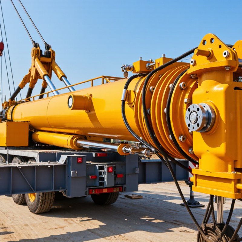
A luffing cylinder must match the crane’s working geometry, not just its headline lifting capacity. Map the boom’s minimum and maximum angles, pin-to-pin distances, and required stroke. Not just reach. Check the load chart across the full radius range, including the heaviest expected load and the boom’s own weight. Then confirm operating pressure, cycle frequency, hydraulic response, and available space around the cylinder. A tight tower site may leave little room for maintenance access. Cold starts, wind, and repeated positioning also change how the system behaves.
Use the crane’s duty profile to specify the cylinder: daily cycles, peak loads, and expected service hours matter. Confirm mounting-pin loads, rod-buckling resistance, cushioning, and protection against side loading with a qualified engineer. A clean calculation can still miss a real shock load. CPWR’s analysis of U.S. Bureau of Labor Statistics data recorded 297 crane-related occupational fatalities from 2011 to 2017, about 42 per year. That figure does not identify cylinder failures as the cause, but it reinforces the need to treat system integration and safe operation as design requirements. Record the assumptions, then check them against site conditions before selecting stroke and force.
| Selection Dimension | What to Check | Practical Guidance | Why It Matters |
|---|---|---|---|
| Luffing-system layout | Direct-acting cylinder, cylinder linkage, or luffing-jib arrangement; number and position of cylinders. | Use the crane’s approved geometry and load chart. Confirm whether cylinders act in parallel and how the system shares load. | The same cylinder force can produce different boom moments depending on the attachment points and boom angle. |
| Required cylinder force | Peak luffing force over the full operating range, including boom weight, rated load, and applicable dynamic effects. | Have a qualified crane engineer calculate the force from the load cases and geometry. For a hydraulic cylinder, extension force is approximately pressure × piston area; deduct system losses and apply the required design factors. | Peak force may occur at a particular boom angle and is not necessarily the same as the maximum rated load condition. |
| Operating pressure and bore | The machine’s rated hydraulic pressure, relief-valve setting, and available pump flow. | Size the bore for the required force at the crane’s specified working pressure. Mobile crane hydraulic systems commonly operate in the several-hundred-bar range, but the actual permitted pressure is model-specific. | A larger bore can increase force but also increases oil volume, weight, and required flow for a given speed. |
| Stroke and installation length | Required pin-to-pin length at retraction and extension, available clearance, and full boom-angle range. | Determine stroke from the crane linkage geometry, then check both end positions and intermediate positions for interference, hose clearance, and adequate remaining engagement. | Incorrect stroke or closed length can prevent the boom from reaching its intended working positions or cause mechanical interference. |
| Buckling and side loading | Maximum compressive load, unsupported rod length, mounting alignment, and lateral loads. | Check rod buckling at the longest effective extension using the actual end-mount conditions. Arrange pins and brackets to avoid side load; do not use the rod as a guide for misaligned structure. | Compression and side loading can bend the rod, damage seals, or shorten cylinder life. |
| Speed and duty cycle | Desired luffing speed, operating frequency, sustained load duration, and heat-management limits. | Estimate cylinder speed from flow divided by effective piston area. Confirm that pump flow, valve capacity, and oil-temperature limits suit the duty cycle. | Higher speed requires more flow and can increase pressure losses, heat, and load-control demands. |
| Load holding and control | Load-holding valves, hose-failure protection, drift limits, and controlled lowering requirements. | Verify the crane’s specified counterbalance or load-control arrangement and its compatibility with the cylinder ports and hydraulic circuit. Do not rely on a cylinder seal alone to hold a suspended load. | Appropriate circuit protection helps control the boom and reduce the risk of uncontrolled movement after a hydraulic fault. |
| Mountings and pin joints | Clevis or spherical-bearing ends, pin diameter, bearing width, lubrication, and allowable articulation. | Match the original mounting interfaces and confirm pin shear, bearing pressure, and alignment against the crane design. Provide the specified retention and lubrication provisions. | Mounting mismatch can create concentrated loads, wear, or binding through the boom’s movement. |
| Environment and materials | Temperature range, corrosion exposure, contamination, and hydraulic-fluid specification. | Specify compatible seals and fluid, suitable rod corrosion protection, and protective features for the intended environment. Keep hydraulic cleanliness within the crane manufacturer’s requirements. | Environmental compatibility affects seal performance, corrosion resistance, and service life. |
| Verification before selection | Crane model and serial data, approved drawings, load chart, and existing cylinder specification. | Confirm dimensions, pressure rating, stroke, end fittings, and circuit requirements against approved crane documentation. A replacement cylinder should not be selected from bore and stroke alone. | The luffing cylinder is part of a safety-critical system; changes can affect boom geometry, structural loads, and rated capacity. |
Note: Selection values and calculations must be verified for the specific crane by the crane manufacturer or a qualified lifting-equipment engineer. Never exceed the crane’s approved load chart or hydraulic pressure limits.
Check the boom’s minimum and maximum angles, pivot distances, required stroke, and available space. Capacity alone is not enough.
Start with the worst-case boom moment. Include the suspended load, boom weight, wind, and changing cylinder leverage. Check force where leverage is weakest.
Bore size and operating pressure determine extension force. Rod diameter affects retraction force. For example, a 160 mm bore at 250 bar produces about 503 kN before losses.
Compare cylinder pivot geometry at both ends of the boom’s travel. Check clearance and cushioning, too. Small errors matter.
Measure pivot centers, pin diameters, and eye widths. Confirm mounting direction and cylinder lengths when retracted and extended. Check twice.
Not without verification. Pivot positions can differ, changing the luffing geometry. Do not guess.
Consider daily cycles, peak loads, service hours, cold starts, wind, and repeated positioning. A quiet test may not reflect real work.
Pause and ask a qualified technician to verify the dimensions. Inspect pins and bushings for wear. A spreadsheet can still be wrong.
Choosing the right Crane Luffing Cylinder starts with understanding how the crane’s luffing system operates and the loads, movements, and working conditions it must handle. These requirements guide the calculations for cylinder force, stroke length, and operating pressure, helping ensure the cylinder can raise and position the boom effectively without being unnecessarily oversized.
Next, confirm that the cylinder’s dimensions and mounting points fit the crane’s geometry and allow smooth movement throughout its full range. Consider materials and seals suited to the environment, including exposure to weather, temperature changes, and demanding duty cycles. Finally, check hydraulic and mechanical compatibility, required safety features, and access for routine inspection and maintenance. A careful selection process supports reliable operation, reduces avoidable wear, and helps the crane perform consistently over time.
